Archive for January, 2008
How do I preserve and save flaking arcade game artwork? (Ms. Pac-man)
Back in December, I managed to be the first in line to purchase an old Ms. Pac-man, sitting in a barn in Sagatuck MI. The game has great pink sideart, and is in really good condition overall, plus, I got it for a song.
Well, it sounds like the game will be making its way down to Indianapolis the week of the 21st – 27th. My main concern is that the artwork has some flaking. I don’t know how to preserve it and clean the machine. There is a good amount of dirt ground into the cabinet, like most old games, but I know that if I wipe the game down I will take some of the artwork with it.
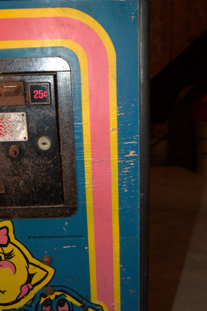
Here is a photo example, the only one I have right now, of an area around the kickplate. I think I read somewhere about putting a clear coat on the stenciled sideart of arcade games to give them a shiny finish, and it also helps preserve the painted artwork.
Can anyone give me any suggestions on how to preserve the artwork on the Ms. Pac-man game, and keep it from flaking and peeling off any further? What cleaner, sealer, or other household product can I use to preserve the arcade artwork?
I did a search on the Klov and Google forums, and most of the flaking is related to glass marquee and bezel artwork, but not how to preserve flaking cabinet artwork. I also did a search on the pinball forums, which seem to have a more rich base of information, and the only tip I found there was “use a sealer”. Just like I thought.
- How do I stop cabinet flaking – Google Collecting Groups
- How do you stop cabinet flaking? – Google Pinball Groups
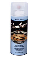
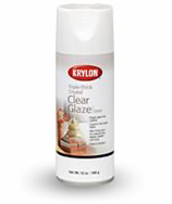
Has anyone used either of these products to seal their flaking arcade cabinet artwork?
The product on the left is Varathane Diamond Water-Based Polyurethane, and the product on the right is Krylon’s Crystal Clear Glaze.
Looking at the website, the Crystal Clear Glaze is advertised as a hi-shine sealer. I imagine that is dependant on the thickness and the coats, but still, that may not work. Thanks to Leinhit for suggesting this to me as an option, whether it may or may not be appropriate for the cabinet artwork vs. glass artwork pieces. Still, my main concern is how I get the dirt off. I doubt that “dabbing” lightly with a wet sponge is going to get all of the dirt out.
Can anyone help me with ideas? Leave a comment with your ideas.
Here are my posts in the different forums about preservation ideas for flaking, if you are interested;
Removing Masking Tape Residue on Arcade Games
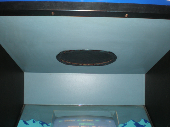
On my long to do list of small arcade maintenance activites, here is a photo of my Pengo.
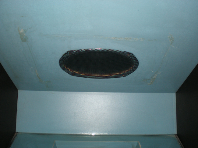
I think the previous owner of this Sega Pengo also couldn’t figure out how to tone down the sound on the game, so they tapes something over the speaker and left it for quite some time. You can see the thick resilient masking tape residue.
Here is what you will need, pretty simple actually.
I started out with a rag and soaked it with Goo Gone, dabbing it on the residue. But I wasn’t able to apply it as thick as I wanted.
Then I figured out to soak the Scotch Brite pad and then apply it to the underside of the cabinet to start to break down the masking tape remnants.
Then, carefully after a few minutes, I scrubbed carefully in a circular motion (not pressing too hard so I didn’t make tiny scratches in the paint) until most of the residue was gone. Here is the underside of the Pengo cabinet under the marquee after I was finished. It isn’t perfect, but it is a lot better and satisfactory for me.
Installing Mark Spaeth’s Jr. Pac-man Toggle Speed Chip Kit
Took me over a month to finish installing Mark Spaeth’s Jr. Pac-man speed up kit, but I can finally rest easy know that my switch is no longer hanging out of my coin door. There was a couple page thread about the kit on the klov forums, mostly people looking to make their Jr. Pac-man gameplay faster. But, towards the end of the thread, there were some good photos and some advice as people started to get the chip replacements in the mail. (more…)
Tutorial for setting up custom permalink structure in WordPress
Changing the permalink structure of my posts had been on my to do list for my WordPress based Rotheblog for quite some time, if not a month after I launched the redesign. I knew my apache server was configured with mod_rewrite available, so I didn’t have to worry about my server not supporting permalinking.
Short Sidebar
Don’t know if your server supports permalinks?
In your .htaccess file put this line of code;
RewriteEngine On
If the engine is not turned on, usually you will get a 505 error screen under certain configurations of Apache. If you don’t get an error, the engine is probably on.
I thought you might be able to figure this out by using phpinfo();, but that was the designer in me not understanding that that function is for php and you are looking for an apache config in httpd.conf.
I had tried setting permalinks up once before, updating my permalink structure in the admin control panel interface, but unsure what to do next as my website links were broken. I thought maybe I had to give my .htaccess certain permissions to allow the system to write the rules to it, but I didn’t make time to explore it in depth. WordPress should update that .htaccess file for you when you change the structure, but double check. Download the file yourself and look.
Turned out today, I tried again without exploring much more in depth, and got permalinking to work. I was nervous, not completely understanding the mod_rewrite engine, that any dynamic links pointing to my site would now be broken. But, the rewrite works on those links, no matter where they are.
Originally, my links were the default, and looked like this;
I added these rules to my Options > Permalinks > Custom Field
/%post_id%/%postname%
This will use the unique post id and then add it to the slug name of the post, which is dynamically generated from the title of the post. (Or it can be entered manually) My links will now look something like this;
www.rotheblog.com/1611/enabling-setup-permalinks-structure-wordpress
Then, all I did was download my empty .htaccess file from the server, and add these rules to it, and publish;
# BEGIN WordPress
RewriteEngine On
RewriteBase /
RewriteCond %{REQUEST_FILENAME} !-f
RewriteCond %{REQUEST_FILENAME} !-d
RewriteRule . /index.php [L]
# END WordPress
I found that these two sites were all I needed to setup my permalinking structure
Now, I can have those keyword rich search engine friendly link titles available to use to my advantage.
For those of you who zoned out in the first sentence and are asking, “How does this affect me?” It doesn’t. It just means that my blog should be a touch easier to find in Google now that the link structure isn’t a variable name anymore.
Questions? Having issues yourself on how to setup your own permalinking structure? Leave a comment and I will help you out as best I can. If I can do it, so can anyone else.
Screen printing / color seperations diagram of Defender marquee
After my post yesterday on “Artwork Bleed for Screen Printing Reproduction Arcade Artwork” I got some awesome feedback from industry experts like Rich at This Old Game, and Brian at Oleszak Creative. As I still grasp at understand some of the ideas in screening arcade game marquees, I thought it might be best to draw up a little illustration to show how I am picturing how a typical marquee would be printed in an exploded view.
Putting accuracy of the artwork found on Local Arcade aside (view my breakdown of the Midway Pac-man sideart artwork inaccuracies), I went out and grabbed the Defender marquee for demonstration purposes.
Defender marquee vector file at Local Arcade – (http://www.localarcade.com/arcade_art/r29.search.htm).
Assuming the colors in this file are correct, and taking each color of Defender marquee artwork and separating them into layers, I would have six layers total, a black, a blue, a yellow, and orange and a red.

As you can see from the illustration above, this is my understanding and how I picture the screen printing order, with the black being printed first (to trap all of the other colors below it, and to hide the bleed) , the blue second, the orange third, the yellow fourth and the finally the red with a white sealing coat over the back. In the illustration, I have shown the Defender artwork in a fashion so you would be able to recognize it, but in reality, the films would be printed in reverse, and if you looked straight down at the marquee, you would also see the printing in reverse. In fact, the Defender marquee artwork might looks something like this;

Plus, this isn’t a really good illustration to show bleed amounts, but I wanted to check to make sure I had the bigger screen printing concepts correct. (I don’t know the detailed history of my games enough to know if the Williams Defender marquee was on glass, or plexi. Probably glass.)
Some good resources that are written simply and helped me get a better understanding on this topic.
- eHow : How to Design a Multiple-Color Stencil for Silk Screen Printing
- YouTube – Screen printing multiple color print video 1
- YouTube – Screen printing multiple color print video 2
Worth a note, I am not starting from scratch on my experience and knowledge base on this topic. I silk screened a couple of shirts way back in 8th grade. How much that counts, not a lot. But it does give me some familiarity with inks, and frames for the screens. But we never “burned” our films, and we never messed with more than one color or registration. These are the areas where I am shaky. A quick (10 minute) search didn’t bring up any visual tutorials on bleeds in screen printing. I didn’t think there would be resources specifically for arcade reproduction artwork screen printing, but thought there would be something else. I must not have searched with the right terms.
So, I need feedback. Is my thinking wrong? Is there a white sealing layer, and what is that actually called? Do you have any good links, or even better yet, and great visual image based tutorials on screen printing that focus specifically on multiple colors, registrations, and bleeds? Leave a comment.
Want a copy of the Illustrator (CS) file I worked on above? Download it here (.zip – 2MB). Edit it and send it back to me if you want, show me where I am wrong. (I just whipped this up quickly, not wanting to spend hours doing accurate separations for artwork I never intended to have printed, so remember this file is for illustrative purposes to help me understand screen printing and films.)
Artwork Bleed for Screen Printing Reproduction Arcade Artwork
If you have been following my blog, I have slowly been working on vectorizing every piece of the original Pengo artwork to have reproductions made for sale. I have another contact that is doing some vectorizing of a couple pieces of artwork, and he asked me if the Illustrator artwork pieces had to have any bleed on them for registration coverage when taking the pieces to the Screen Printing stage. I knew from working with Brian at Oleszak, that there needed to be some offset bleed on the shapes when making stencils, but I figured this was more for the home arcade game collector, who generally wouldn’t know much about registration for different colors of artwork. A “CYOA” kind of nicety.
So, I emailed Rich at This Old Game. I asked how much of a bleed he would add to individual shapes. 1/8″ bleed seemed too much to me for finer details, but for the larger details, only adding 1/16″ – 1/32″ didn’t seem hardly enough to make a difference. This is what he said;
Basically, to allow the color laps about center of the Black detail that it would cover. Also white is usually full coverage on the back of 2nd surface prints. On fine detail, I go in and just split the difference in specific spots where the thickness of the black may vary. But to answer your question, I do tend to add approx 1/8″ bleed unless that bleed doesn’t fit the artwork then I have to manually go in and split that difference. Any text I usually outline 5 to 10 pts.
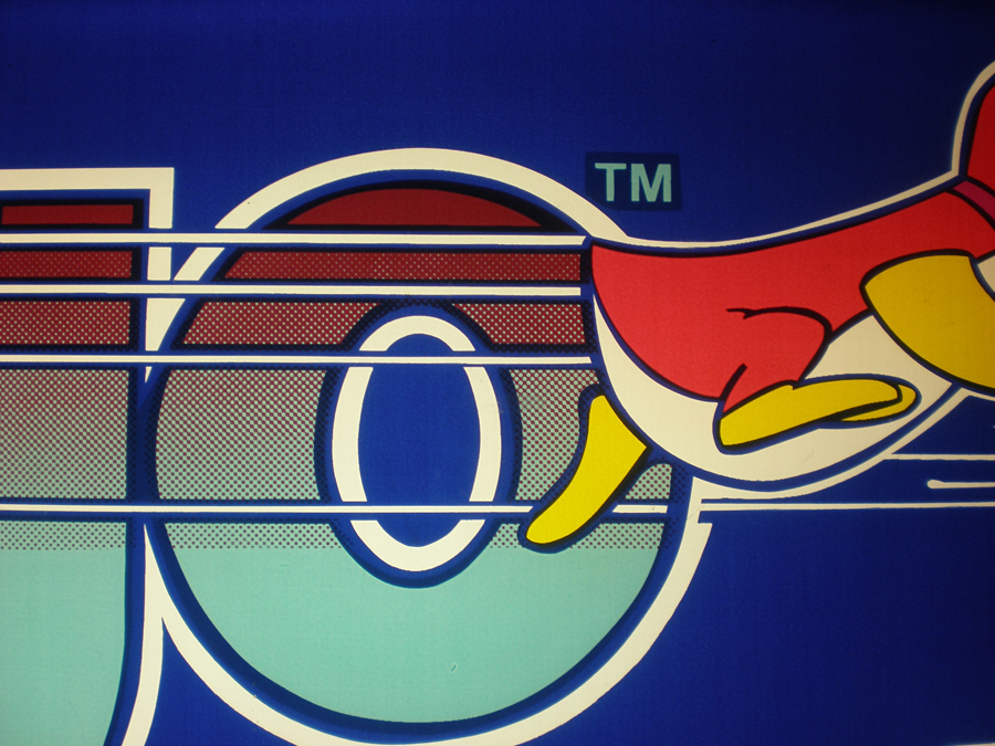
I got a file from him, demonstrating some of this, but I don’t completely understand all of the concepts for screen printing reproductions yet. If you don’t have any idea what I am talking about, here is a photo of my Pengo marquee. You can see the bleed for the “TM” text showing through, as well as some of the halftone patterns and other pieces of artwork that overlap to make sure there is enough coverage.
The main idea I got from the information he sent was, yes, add bleed to the artwork to help with registration of colors, and it is a judgement call based on the detail of the artwork. The finer details of the reproduction arcade artwork add 1/16″ to 1/32″ of an inch bleed, and on some of the bigger, thicker details add 1/8″. (Not to mention, even though I didn’t ask this, I am sure that I need to start separating my artwork in colored layers) I know that both Brian and Darin read what I write here when they have time, and I figured they could lend their expertise in the information, or even Rich if he stops by. My main question remaining is what Rich said above;
Also white is usually full coverage on the back of 2nd surface prints.
Rich is the absolute best in terms of response time, although his emails are sometimes hard to understand because of the way they are worded. Here is a tight crop of the final prepped file he used reproduce the Professor Pac-man overlays from my vector artwork.

This looks exactly like the “TM” above, except, if the text is yellow, why have the color “white”. Wouldn’t that bled color be yellow there, showing really fat lettering?
So, there is a lot of work to do, added work to the final vectorizing Pengo files that I thought I had finished. But, they need to be right. I haven’t added bleed to any of them, so I will have to go back through and do that. Here are some close up details of my start to adding bleed to the Pengo artwork. There is a before vector trace (Purple Outline), and an after vector trace with the additional bleed (Light Blue Outline). (And after I got into the file and tried it for myself, I found that even 1/32″ bleed would overlay some of the surrounding pieces of artwork, and that I had to go down as small as 1/64″ (.016 of an inch rounded) bleed to prevent overlap.)


Pengo Locked Up During Gameplay
I had never had this happen before today, but today it happened twice when I was playing my Pengo arcade game.
The first time, a sno-bee got stuck at the top of the screen between two ice blocks, and just kept bouncing there. I didn’t mind, because that meant I could go around the playing field and match up the diamond blocks for my bonus points. I was able to break one of the ice blocks that Sno-Bee was wedged against, and then I smashed him with another block.
But the second time in less than 10 minutes, I was trying to match up the diamond blocks, so I decided I would guide Pengo up next to the dormant Sno-Bee. Well, some of the game code stick executed, Pengo died when he touched the Sno-Bee, but then, the game just sat there, playing the music. Check it out;
I had to turn the upright machine off and back on again. I hadn’t even seen this error in Pengo that causes it to lock up, or freeze. I know sometimes I can run through some of the ghosts in Ms. Pac-man, and even in Pengo, it seems like I get lucky either touching a Sno-Bee without dying or running through one. But not in this case.
Anyone else have this issue with their Pengo PCB board? Is it just mine? If you have issues, does the Sno-Bee only get stuck at the upper right of the play field? Or is it only one board configuration? Or maybe this is just this revision of the PCB, since I know there are a couple. Voice your thoughts.