
Where on an Electrohome G07 is R1?
I spent..a stupid amount of time trying to figure this out, and am going to bed without a true solution. So, if you have used Randy Fromm’s flowcharts for troubleshooting an Electrohome G07 monitor and can help me out, that would be awesome.
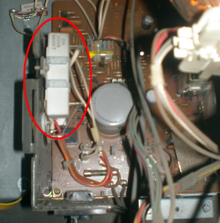
The big mysterious ceramic resistor hanging on the side
Troubleshooting my brand new Mad Planets tonight. Oh yeah, did I mention, the monitor went out? I don’t feel like lately my luck has been so sweet.
I am using Randy Fromm’s flowchart (Sort of a which way diagram written for the average person with basic instructions) to troubleshoot why I am getting no picture and the game is playing blind. It’s an Electrohome G07-907. I have continuity on both fuses – F901 and F902 – so I kept moving through the chart for Randy and I quote;
Check the regulated power supply at resistor R1 (that’s the 220 ohm, 25 watt, giant, white ceramic resistor that’s hanging on the side of the chassis.) The terminal closest to the CRT (with the white wire on it) should measure +120 VDC.
Big and white – check. It’s more of a rectangular white box, if we’re talking about the same thing. It’s labeled with 220 ohm, 25 H. I don’t know what H is admittedly. I don’t think that is synonymous with Watts. Here is the photo;
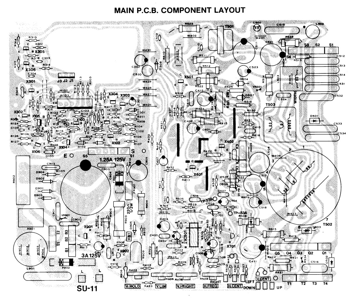
The only problem is, on the schematic for this monitor that I pulled up, that white rectangle, ceramic or otherwise is labeled as R902. So, that can’t be right. Here is a detail of the schematic, click for a larger view;
I still can’t find the R1 resistor
Even if I were to believe that somehow there was a typo, and Randy said R1 where he meant to say R901, the schematic shows R901 directly below R902 on the side of the chassis frame. However, I have no R901. So….I am a little bit lost. I checked out Bob Roberts ‘Capacitor Map’ for a G07 monitor, and that didn’t help point out R1 either.
Regardless, I tested R902 with the power to the game on. I got a reading of 0 VDC on both the lead closer to the CRT monitor and the lower one, which should have read 120 VDC and 145 VDC respectively. All the more enforcing the idea that I don’t have the right piece.
If you can help point me in the right direction of where to look on that crazy schematic, that would be a huge help. Or give me some insight into Randy’s flowchart for troubleshooting this arcade monitor.
Update – 6.19.08
This is the first troubleshooting I have ever really done, beyond – Ohp, do a cap kit. Come to find out, R1 must be stamped into the chassis itself, hence why I can’t find it. I will probably do a simple test when I get home on the HOT. Apparently, touching the casing of the HOT with one lead and then touching the metal frame right by where it is mounted should not show any voltage due to the insulation. If it does, then the HOT is bad and therefore the flyback.
Here are some similar arcade posts
- Starting to fix a Ms. Pac-man playing blind
- 19K4635 Wells Gardner Monitor – Difficult to do a cap kit
- Visually Damaged Components
- Troubleshooting Pengo Power Supply
- Wizard of Wor Capacitor Problem
If you enjoyed this post, please consider to leave a comment or subscribe to the feed and get future articles delivered to your feed reader.
Comments
The one circled in the photograph is R1. There are two resistors there. The board diagram shows a resistor at R902 which is mounted to the PCB. The one mounted on the wall is R1 and is suspended ABOVE R902. Typically Electrohome stamped the part number in the metal on the wall next to the mounting point of this type of component. PCB diagrams ONLY include what is physically mounted to the PCB and not parts mounted elsewhere and suspended above the PCB…
@Jamie,
I even emailed Randy himself, but his answer…well the jist was basically what the description said, big and white, and he referred to it as wirewound. I have a guess what that means, maybe if I opened up that white casing. But it didn’t really help any. I was hoping to not have to buy a larger kit, but you are probably right, it probably would be a good idea either way, and in the end I probably will get the full cap kit with flyback from Bob Roberts.
@Mongo
If you couldn’t tell, I didn’t take out the chassis yet, it was a long night. But, looks like I will do that next so I can see the stamping, and get at the other resistor. But the information that you gave here helped clarify.
I was getting out 0 VDC…I don’t have the flowchart in front of me, but that would mean one of the fuses is blown right? Even though I got a good continuity test from each. Which in turn, would mean to replace the HOT / Flyback anyway. Right?
Yeah, those white ceramic resistors are wirewound. I actually checked the parts list in the manual for a G07 and I don’t see any resistors labeled as R1. I see other people referring to that as R1 so I guess that’s right, but seems strange. Every component that I can see has 3 or 4 digits.
Considering Jeff got a bite from the voltage in that cap, my guess would be bad HOT and flyback based on Jamie’s comments. That’s probably the issue with the one we pulled from pengo as well…I don’t think Mongo replaced the HOT, did he?
Your F902 is soldered to the board right? I’ve always heard you have to remove fuses from the circuit to get an accurate reading. Not sure if that’s a wives tale or not. Bob’s deluxe kit comes with that fuse BTW.
After doing a deluxe cap kit on my Galaga 3, my dead G07 came to life! 🙂
I had a dead monitor in my new Centipede. I did the deluxe cap kit also, and it worked great. I had a blown fuse (the smaller one) that was right beside the large cap, which causes that cap to hold a charge. I read online to discharge the cap too, and of course it popped when I hit it with the screwdriver. Glad I got that advice before poking around with the board! I think my issue was with the HOT because of the measurements I obtained before replacement. It was also the first time I replaced a flyback. What a pain to remove the old one! What do you guys use to put the wired boots back on? Is there a recommended glue to hold it on? One of mine was slightly torn, and I would like to secure it a bit better than just pressing back over the solder joint.
@Mongo,
Ok, I tested for continuity on my HOT, and I do not have continuity.
So, is this information at 2coinsperplay.com talking about the B+ the next step I want to look at then? This first read here would imply that this test would be for a monitor that comes on occasionally….
Is the ‘deluxe’ cap kit labeled as such on Bob’s long scrolling website? Is it on the cap kits page? It must be the Electrohome G07 Repair Kit for $26.00.
“that big gray cap will still hold a nasty charge. If you take the chassis out, put a screwdriver across the leads on the bottom before touching that area. You should get a nice big cracking sound if that’s the case.”
I’m about to do a G07. Do you just touch both leads at the same time with a screw driver to discharge this? Do you need to ground the screw driver?
I believe I might be able to come up for air this weekend, and finally perform this monitor rebuild.
I also read that you can take a lightbulb and touch it to the leads, when it dims you know it’s been discharged. I’ll probably skip that and just ground it with a screwdriver. I’ve already been nipped by it once.
I have a Go7 for star gate and as soon as you plug the monitor in and turn on the machine it blows the transformer fuse, when the monitor is not plugged in the machine stays on and the transformer is good? Could it be bad fly back from the monitor also?
The schematic is marked R01. The 3 leads from it are wire-wrapped to posts on the pcb which are marked B1, B2, and B3. The R901 you refer to is mounted on the pcb is smaller than R01 but much higher in resistance value.
Leave a comment
Your email address is never displayed and cannot be spammed. If your comments are excessively self-promotional you will be banned from commenting. Read our comment privacy policy.


June 19, 2009
I don’t believe there is an R1. That one in your pic should be the one he’s talking about.
I’ve had a few dead G07’s, and they all were due to bad HOTs and flybacks. I usually get the deluxe cap kit from Bob Roberts that includes the flyback and HOT, put all that in, and its brought every one of them back to life. The original flybacks in G07s are known to fail regularly so even if the flyback is OK now it should be replaced anyway if it is an original.
If the HOT (or flyback? can’t remember) dies, that big gray cap will still hold a nasty charge. If you take the chassis out, put a screwdriver across the leads on the bottom before touching that area. You should get a nice big cracking sound if that’s the case.