Arcade Projects
Wizard of Wor Resetting
Wanted to try the game again tonight to see if I had any problems with it resetting. Well, after turning it on, that is all it did, every second it reset and the game just kept flashing, so there is something wrong with it. Some information is turning up on the Google Groups, it may not be too complicated to get working again.
I also spoke with Rick tonight, and he was fairly familiar with the hardware in these Wizard of Wor machines. Made by Midway / Bally, the hardware is very similar (which I already read) to Gorf, and apparently Professor Pac-man. He said it sounded like a Z-80 processor possibly going bad since there is already a switching power supply installed. He said it can never hurt to clean the edge connectors, all sorts of weird problems can happen there. As I had read before, and he suggested again, to use Scotch Brite pads. I have to figure out which ones. I have heard about using the magic eraser ones, but apparently that isn’t what you use for edge connectors.
Picking up the Wizard of Wor
I went today, on what ended up being a hot day, to get the game. I took a look at it briefly when I got there. The previous owner showed me that the game had problems with resetting. He started to play his game, was a minute into it, and the game reset. When I took a look at the back of the game, I noticed that the back door was loose. The top wood had splintered, so it didn’t really sit in place. So my thought is, maybe the movement of the game play moves that door just enough to hit the switch in back and reset the game occasionally.
I played the game when I got home, and it didn’t reset on me at all. I had taken the back door off and pulled out the switch, so I thought my theory seemed to be valid. There are still lines through the screen, and I am having problems locating the monitor model. It is some sort of Wells Gardener with an RCA tube. I have a number, but it doesn’t look right. It will need a cap kit, and that is an easy fix if that is all I need to do. The chassis is just caked with dust, so although whoever restored this game with a brand new control panel didn’t do much to the monitor. He did put in a switching power supply to switch out the linear one in the game.
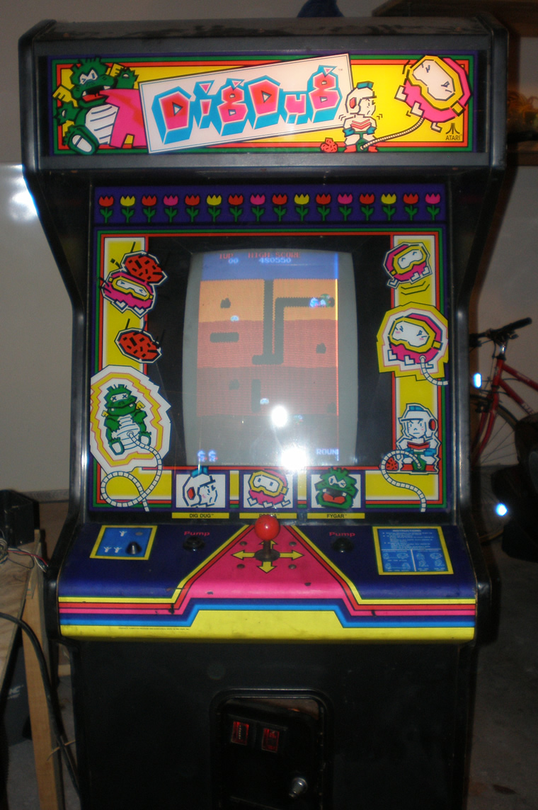
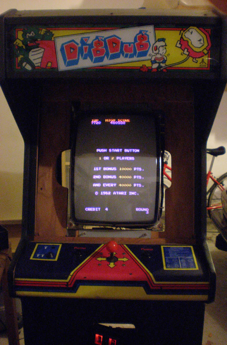
Adjusting Dig Dug Color, now it looks great!
This afternoon I took some time on the Dig Dug outside to see if I could figure out what was going on with the color issues. I took my huge oversize mirror out so I could see what I was doing. I was able to adjust the vertical sync a little bit more to get the picture right, and then I adjusted the color controls, mostly adding more blue into the picture and the game looked great!
I was pumped. I was starting to get nervous that somehow I had did some of the caps wrong. I knew the color caps shouldn’t be on the main chassis, but again, don’t know that much so who knows what all that affected.
I got the paper bezel out, and brought out the glass one with artwork from the basement and put it all back together. Pretty exciting to have the Dig Dug game in a working condition. I also put in a new lightbulb into the marquee and everything lit up just fine. The sound was defening, just like the Pengo, and I couldn’t figure out what to do. I looked at the schematic, and I could tell that there was supposed to be some sort of sound control inside the coin door. Well, turns out, the little control mount inside there that I got off ebay was missing the knob for the sound dial. I only figured that out when I compared it to what I had on the Dig Dug inside the house, which still had the dial. My old control mount from when the game was still a Land Sea and Air didn’t have the dial either. It seemed like it was well mounted on the machine it was on, so I don’t know why the other two mounts had lost it.
So, I got the metal peg to turn and make the game playable sound wise. So, for now, the game is done. I listed the one in the house on ebay, so now I have to figure out what to do with this one. I have to work on the cone one and two player buttons on the Dig Dug outside a little bit, but that is the last piece to finish.
New Dig Dug Coin Door Amp Connector
Got the new AMP connector hooked up with the old coin door wires tonight, so that was pretty exciting. I coined up and played just fine, the coin door bulbs even came on. However I realized I hadn’t hooked up the Player 1 and Player 2 LED Cone buttons. So I had to go inside and check the connections on the other machine. The one button has solder on it for some reason, so I may just swap that one out. It has a broken cone, so it doesn’t even stay in the hole. I also had to re-attach the right side pump button.
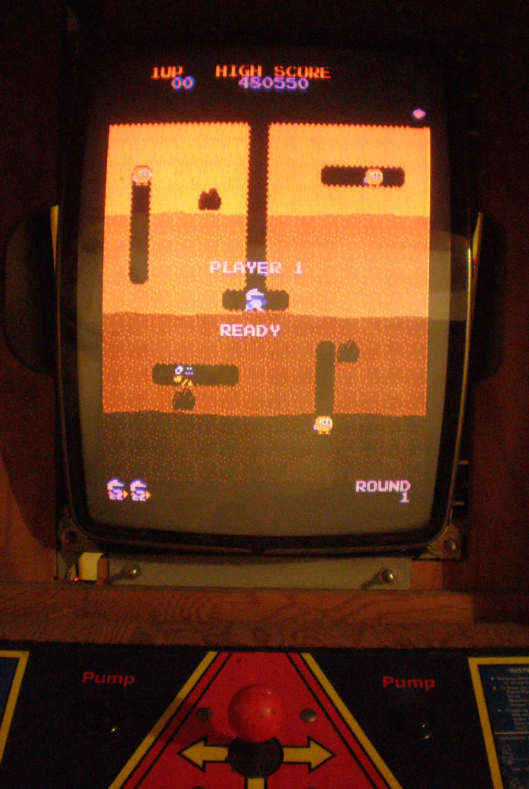
But other than the fact that there was quite a red tint to the game, I got to play it tonight. The alignment is off a little, the guys look a little funny. I also noticed that the marquee light didn’t come on, so I have to figure that out. Plus, the sound, is deafening, just like my Pengo. I will have to see if there is a Pot for that somewhere, and if it is working.
So, every time I think I am close, there is something else minor going on. But I think I am still going to try to list the other game this weekend.
Troubleshooting Pengo Power Supply
Spent a couple of hours tonight looking at the Pengo game and trying to do some troubleshooting, mostly on the liner power supply.
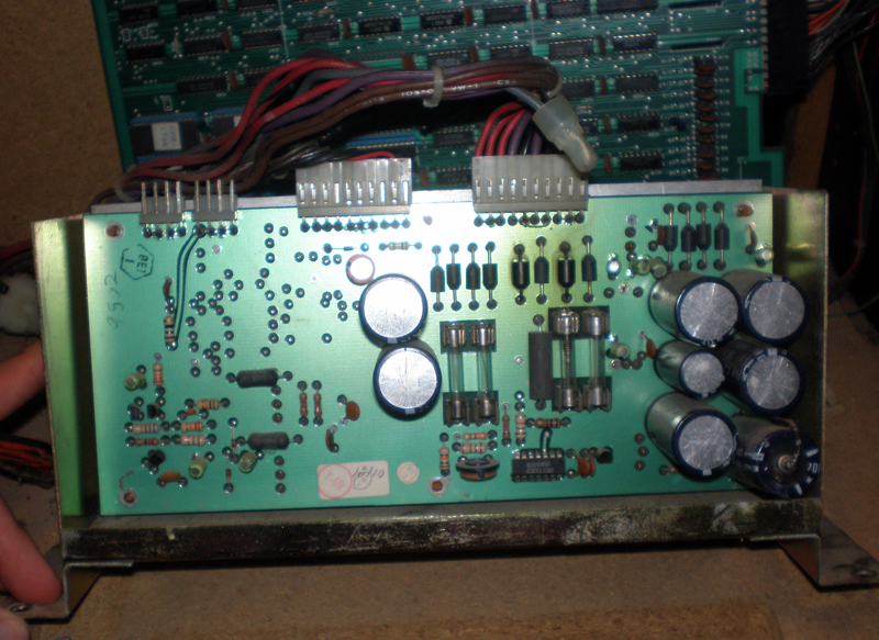
As you see in the photo below, this is what a Sega/Gremlin Linear Power Supply looks like fromt the front, with the PCB board mounted on the inside of the humongous heatsink.
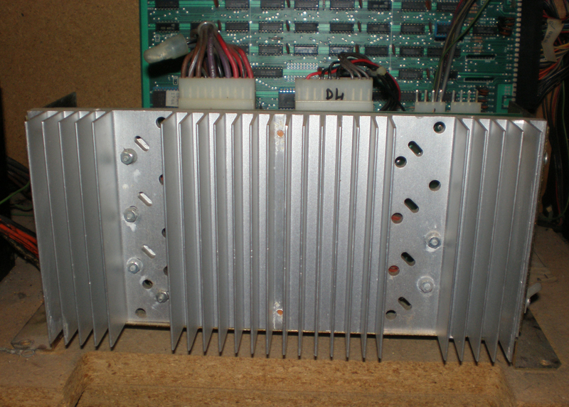
I had made contact with two different people who said to start by testing the Power Supply Voltages. The Power Supply in this machine is mounted awkwardly, so I just decided to unscrew it and get rid of some of zip ties. Most collectors like their games to be perfect and neat, right now, I just want to understand them and care little about that.
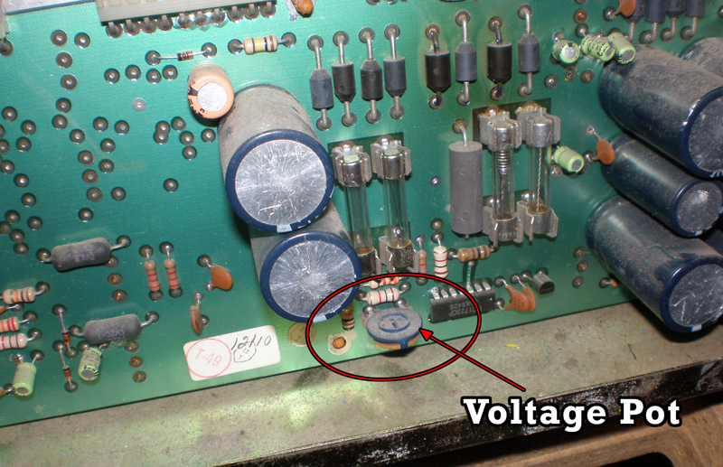
I took out the first two fuses and checked for continuity, and those seemed to be ok. (Those are the fuses on the left in the photo, just above where I indicated where the pot for controlling the voltages is at.) So, now time to check the voltages.
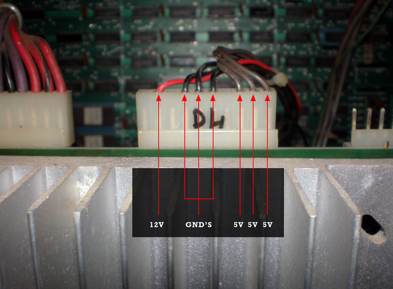
These second two photos above show the power connection for the 12V, 5V and Ground connections that supply the PCB. The 12V would be for the audio, and the 5V for the game board. I stuck my black lead into one of the ground, set my meter to 20V, and put my positive lead into each of the 5V and 12V connections, four tests in all.
For each 5V I read 5V exactly, and the same with the 12V, I read 12V exactly. So know that voltages can be dropped on the way to the board, I checked the voltages in the connector. Same thing, all of them right on the money which is weird, they usually fluctuate about .2 a volt. So, I decided to test right on the traces for the edge connector. I am going to point those places below, as well as the pinouts for this 44 (22×2) pin connector for the Pengo.
Should I replace the Stern Frenzy Ribbon Cables?
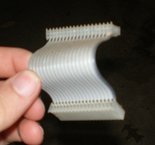
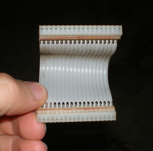
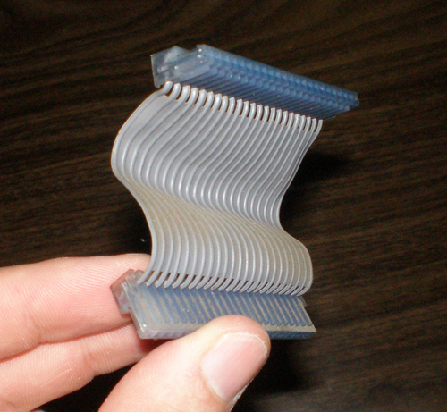
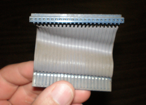
I started to think that maybe the ribbon cables were bad, I read that these were also a source of problems with the game. I read in posts that people have replaced Stern’s ribbon cables in a number of ways. Either they find a known working set on ebay, they find exact cable replacements for the pin configurations, or in some cases they make their own.
I read somewhere that people used scsi cables as replacements, but I didn’t find that to be true. Scsi cables are pretty huge, and regular ATA cables where usually in configurations of 20×2 = 40 pins, or 22×2 = 44 pins. The two cables I took from the Stern Frenzy game where in configurations of 23×1 or 18×1. So, without knowing for sure if they were bad and pumping more money into a game I wasn’t going to keep, I decided to wait and see if another solution presented itself.
Amp connector on the way
Tonight was a fairly exciting night. I spoke with another really helpful, really intelligent collector who helped me understand something that should have been simple but I just didn’t see myself. The 2×3 AMP connector coming off the EZ20 monitor was indeed for the RGB Ground and Sync.
The Red and Green wires terminating in a molex connector were for the power, the colors and location were just throwing me for a loop. I looked at the old harness I took out, and sure enough, there was the 2×3 AMP connector, and then pigtailed off of that was a regular .156 headers for the RGB and sync as well as the ground as a seperate connector. Fortunately the wire colors were the same, so all I had to do was snip that whole piece off, and match up the same wires together on the original harness. I did have to “hack” the original a little bit, cutting off that RGB Sync and Ground connectors there, but in this instance at least I would have both options for the future no matter what monitor.
So, I matched up the wires, soldered them together, connected the 2×3 AMP and let the unused RGB sync and ground dangle, wrapped up the soldered wires in electrical tape and plugged it in.
I got a picture! Yes! Not only that, but I got sound! The picture is messed though. I just did new caps, and there seems to be a color missing the screen is really yellow.
This collector that helped me out on the phone also talked to me about the power supply. He says that Bob Roberts makes a kit to do some replacement of different parts on the power supply. The big blue capacitor can cause a lot of problems, and it also come with a new fuse block and fuses and some other stuff. He said this is worthwhile to get. He also said that the audio board is also actually a linear power supply, so it is important to get the schematic and see if it is putting off the correct voltages to the PCB, otherwise as I have learned lately, the incorrect voltages can damage the ROMS, RAMS, EPROMS and any other matter of things.
I still need to attach the AMP connector to the coin box so I can test that out. I hope to do that here in the next day or two.