Archive for June, 2007
Final Dimensions for Agent X Kickplate
I got the dimensions for the artwork over the weekend, so I decided tonight I would give it a shot and see how far things were off in terms of real dimensions.
The dimensions I was given for the Agent X kickplate artwork are; (Mind you, these are the same for a Crystal Castles and I even think a Star Wars cab)
- Total Height of Kickplate / Coin Door Area = 29.625 in.
- Total Width of Kickplate / Coin Door Area = 23.75 in.
- Total Width of Coin Door (To Outer Frame Edge)= 8 in.
- Total Height of Coin Door (To Outer Frame Edge)= 20 11/16 in.
- Measurement down from top of kickplate to top of Coin Door edge = 1 1/2 in.
I don’t have a measurement from the left or the right of the kickplate to the inner edge of the Coin Door, which would give me very precise alignment, but this isn’t a film but a replication, so it will never be perfect.
When I made my Illustrator canvas the right size, and scaled everything up, I did really well. The Coin Door fit perfect in the spaces drawn for it. The only thing that I need to make a decision on is that the artwork is a little tall. There is excess border on the top, so nothing important that would be cut off for the most part. Now, I could just cut it off, and actually lose one green circle on the right, or I could scale it down to fit. It wouldn’t be proportionate, but for about .75 of an inch, you wouldn’t even notice the distortion unless you had two machines side by side. But one thing is for sure, I probably won’t go back and readjust all of the artwork just to get that green circle in the printing area at the top right.
I have to talk to Richard to kind of see what he thinks.
Amp connector on the way
Tonight was a fairly exciting night. I spoke with another really helpful, really intelligent collector who helped me understand something that should have been simple but I just didn’t see myself. The 2×3 AMP connector coming off the EZ20 monitor was indeed for the RGB Ground and Sync.
The Red and Green wires terminating in a molex connector were for the power, the colors and location were just throwing me for a loop. I looked at the old harness I took out, and sure enough, there was the 2×3 AMP connector, and then pigtailed off of that was a regular .156 headers for the RGB and sync as well as the ground as a seperate connector. Fortunately the wire colors were the same, so all I had to do was snip that whole piece off, and match up the same wires together on the original harness. I did have to “hack” the original a little bit, cutting off that RGB Sync and Ground connectors there, but in this instance at least I would have both options for the future no matter what monitor.
So, I matched up the wires, soldered them together, connected the 2×3 AMP and let the unused RGB sync and ground dangle, wrapped up the soldered wires in electrical tape and plugged it in.
I got a picture! Yes! Not only that, but I got sound! The picture is messed though. I just did new caps, and there seems to be a color missing the screen is really yellow.
This collector that helped me out on the phone also talked to me about the power supply. He says that Bob Roberts makes a kit to do some replacement of different parts on the power supply. The big blue capacitor can cause a lot of problems, and it also come with a new fuse block and fuses and some other stuff. He said this is worthwhile to get. He also said that the audio board is also actually a linear power supply, so it is important to get the schematic and see if it is putting off the correct voltages to the PCB, otherwise as I have learned lately, the incorrect voltages can damage the ROMS, RAMS, EPROMS and any other matter of things.
I still need to attach the AMP connector to the coin box so I can test that out. I hope to do that here in the next day or two.
Replacement cap for Frenzy ZPU1001 board
Tonight I stopped after the gym at Radio Shack to get a replacement capacitor for the ZPU1001 board. I didn’t want to travel all the way to Meunier for one cap. I soldered it in and put the board back into the cabinet and got….nothing.
I got a white screen again, which was quite disappointing. The board was dry from the scrubbing, there was no reason it shouldn’t work. But, I did also have some problems soldering, the iron I have is about shot (which is fine because it was free). I don’t know what a cold solder joint is, but maybe that is what happened. Is a cold solder joint when you have old solder with new solder on top and the electricity doesn’t flow between them? All I do know is until I took that board out and scrubbed it and replaced that cap, I at least had garbage on the screen.
Here is what I expected to see like the first time, the Frenzy garbage on screen.
Figuring out the EZ-20 Monitor hookup
Realized I grounded the monitor wire to wood, doy! So I put that in the right place. Brent and I have beeen emailing back and forth. He has a Kangaroo he is going to try to take photos of the inside hook ups, but it sounds like I am not crazy, and there is a different way to wire an EZ 20 than a regular monitor. It is almost done, and it is bugging me that it is this close. But, I should be able to sell the working Dig Dug really soon.
Working on the Frenzy game.
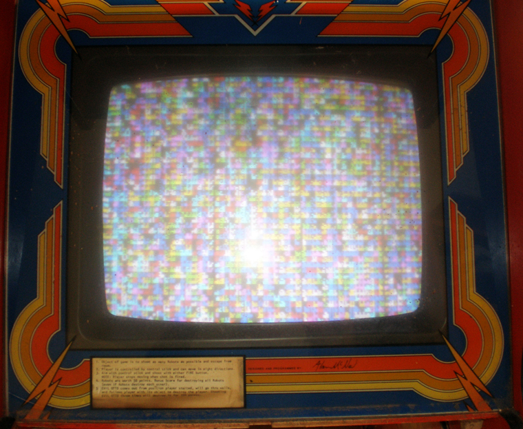
I got out into the garage and started drinking around with the Stern Frenzy game. I did some testing on the fuses and determined that at the very least I needed to replace a couple of those. So, I took a short bike ride up to Radio Shack and got some. I couldn’t nail down which ones were bad, so I just covered all of my bases and got replacements for the ones in the power supply and on the Frenzy logic boards.
I switched out the fuses and lo and behold now instead of a white screen on the Frenzy monitor I am getting a bunch of square pixels on the screen. That is encouraging. I did some more research on the Frenzy ZPU1001 board inside for what to do next. Most of the posts asked about what to do about acid damage on the Frenzy board. Always acid damage, it was so common. I didn’t initially notice much battery acid damage, I noticed some discoloration and dripping where some of the connections were green, but I thought battery acid damage would be more like a fire or something, very obvious.
I already had taken off the battery used on the ZPU1001 yesterday and thrown it away, so I figured it had to be a different problem. I tried readjusting some of the connections to see if that helped at all. It didn’t, so I went back to the posts. Some of them suggested neutralizing the acid damage with another agent and scrubbing the back of the board. I knew I didn’t pay much for the Frenzy game, so in the end I decided to be brave.
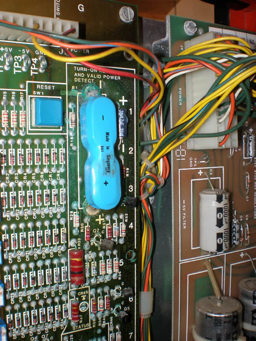
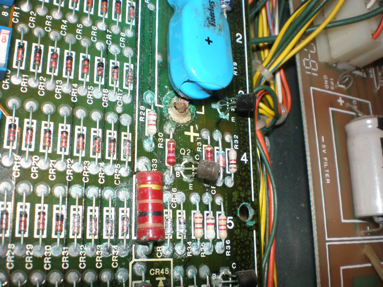
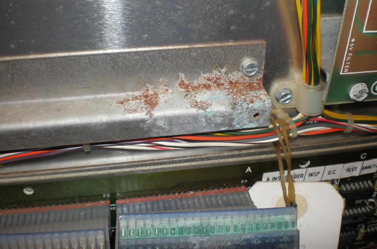
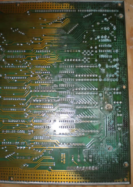
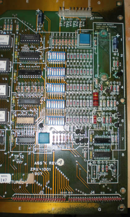
I removed the main processor board that had the battery leakage on it and once I looked at the back of it I realized how bad the leakage was. You could see discoloration over almost a third of the board, and all over the traces, probably gunking up everything. In the photos below you will see the contrast, on the front it is hard to tell and then how obvious it is on back.
I scrubbed the back of the traces with a vinegar water mixture. There was one capacitor that should be easy to replace in the leak zone, so I took that off as well. It was all bubbled up, so I figured that couldn’t be good. I could tell now how bad the acid leakage was because the solder was really hard to get flowing and get the cap out.
Here are some photos of the Frenzy PCB board, battery and the leakage down onto the ribbon cable below;
I have to let the ZPU1001 board dry for a day or so, so I just left things for now. I started to clean down the rest of the cabinet, mainly the top, and two of the buttons that wouldn’t even press anymore because of the crud in them. I put the buttons in a CLR mixture to loosen up the gunk. After cleaning the board the dirt was loose enough to scrub out with a toothbrush and put back in the panel.
I am going to go and get the replacement cap here in the next day or two, and cross your fingers, hopefully the game will work.
June 16, 2007
Today we took Nokes over to Christine’s to meet with Lady on her turf. Things went well, it was playful. We let them out back and Lady just ran circles around Nokes and the barn. I have video of that. Then they came inside and wrestled, Nokes battled at Lady’s head and they kept mock biting at each other’s ears and head. They never really left each other alone until we took them on the actual walk, then they cared little about what the other was doing. It was short, just around the block because it was so hot, but I think any doubts I have are gone. I think they will have no problem playing good together later this summer.
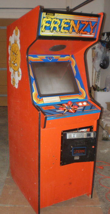
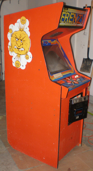
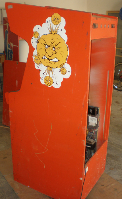
Got the Frenzy home today
I had some help in getting Frenzy today at lunch, and I got home from work at a decent time so I got to dink around with the game a little bit. I called Joe in Chicago to hear his thoughts and talk a little bit of gaming with him. I turned the machine on, and got a white screen which means there is power, but there are some other major issues. I should be able to check that out a little bit more tomorrow.
Here are some photos of the game;