How to identify this Nintendo VS. Game Board
There are two websites that are really great for identifying an unknown arcade game board (PCB), PCB photos at Xmission and the good old Crazy Kong website. I have a number of websites bookmarked as PCB identification resources, but these two are the best. (more…)
Figuring out OL, OH Dig Dug PCB error
I have gotten a little motivation back, and took a little time to investigate this further.
I had been going back and forth with Bob Roberts on this chip, and without even looking at my board I was able to kind of figure out with his help that this chip was plug in play, which meant it should be socketed and no soldering necessary. Plus, since it was PnP, that meant I didn’t have to burn anything to it either. He said the chips are very sensitive and this is fairly common.
In the Dig Dug manuals, it says that a OL and/or OH error are due to a bad RAM. It just depends on what version of the Dig Dug PCB you have to find the location on the board. If you have Revision A, the position is 9M, and if you have Revision B of the PCB, then it is position 4K.
I thought for sure these positions would be printed in the manual, but they weren’t. I pulled the board out and did a comparison of component side elements on the board to the two drawings in the manuals. I have a Revision B Dig Dug PCB, so that meant my bad RAM was at 4k.
Here are some photos of the PCB. I circled the 4k labeling, it might be hard to see. Also a photo of the bent RAM and the RAM in the socket.
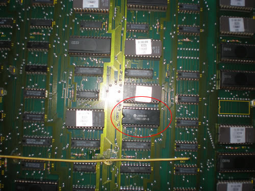

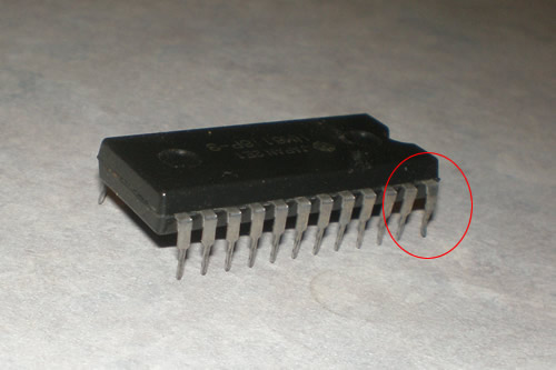
I took a look, and it was obvious. There my RAM set, with the front leg bent and barely in the socket. I was floored, how had it worked up until now? It might be as simple as taking that chip out, bending the leg back, and the game might work. Well, I did just that, and it didn’t work. So I am guessing that after so much time of it being almost bad corrupted the chip.
I am checking with Bob to see if he has that chip. The number on the top of the Chip says JAPAN 2E1 HM6116P-3. Would like to get a larger order of stuff to bring down the total cost for the one part, but if it means getting the game sold, I may not wait.
Missing Monitor hookup for Jr. Pac-man
Sent payment for the Jr. Pac yesterday, so I felt comfortable asking Rick how to hook up the monitor. After a series of emails, it came out that the monitor hooks into the top of the PCB on the right side. There is another connection on the left side as well that attachs right into the harness. There was no connector on the right side, and I looked inside the game in case it came loose, wasn’t there either. So it sounds like he is going to send it to me in the mail today so I have it by Wednesday or Thursday of this week. I was really hoping to play it sometime before Friday for sure.
Plus, I had forgotten about the monitor brackets. He had mentioned that original Jr. Pac owner had taken them out with the monitor before Rick bought it. The Pac-man ones I have won’t work, just a little too short. I am going to try to go to Home Depot this week and try to find something that will match, I have read in the forums that people have found things. I also need some tinted plexi, but I am less worried about that right now…
Other info about the game…The swelling that I mistook for water damage towards the back of the cab can just be caused from heat he said. He said he sealed it off, hopefully preventing any more swelling. That makes me glad it is sitting in the garage now that it is a little cooler out. I also identified the serial no. #333, it’s stamped on the back of the cab above the back door. The Mappy serial is stamped there too. The Serial is in the cab still too on a piece of paper, A29-00333, and you can see where the old Mappy tag was on the harness.
Rick also said that the tracks that are in the bottom where the new switcher supply is are for the old linear power supply board that almost always fails in these games.
Photo of Wizard of Wor PCB
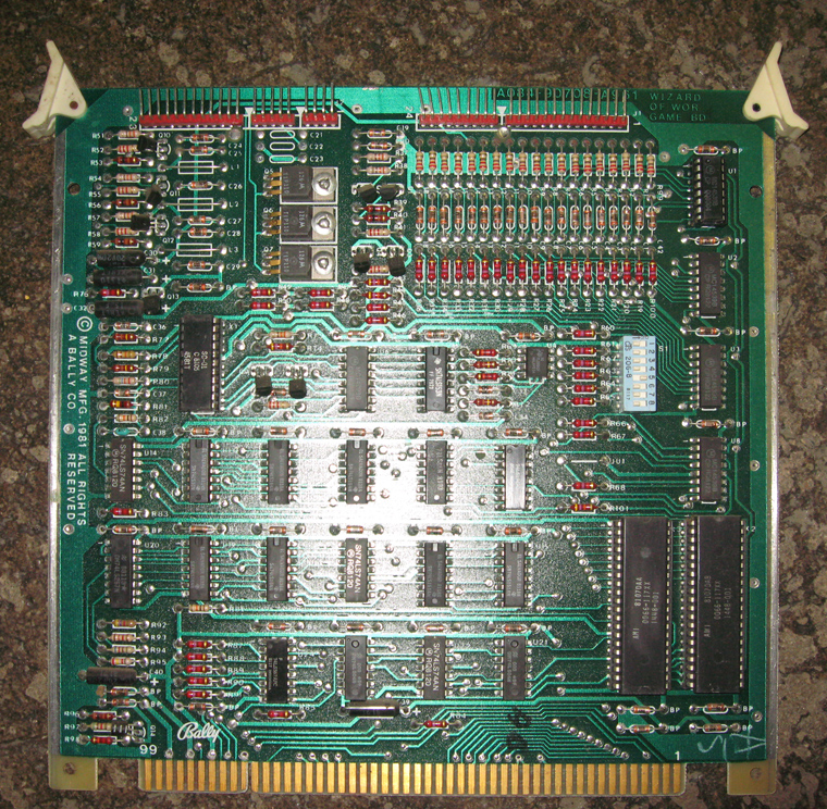
Got a photo today from a collector of their Wizard of Wor PCB. They have a cabaret version of the game, however, and after looking at the photo and looking at the owner’s notes, the Wizard of Wor PCB for a cabaret is a little different than the dedicated upright version.
Here is the photo if you are interested.
Replacement Capacitors for Wizard of Wor PCB
Got my order from Bob Roberts tonight as planned. I did end up getting some sort of replacement for the original glass caps used on the Wizard Of Wor PCB, here are what they look like.
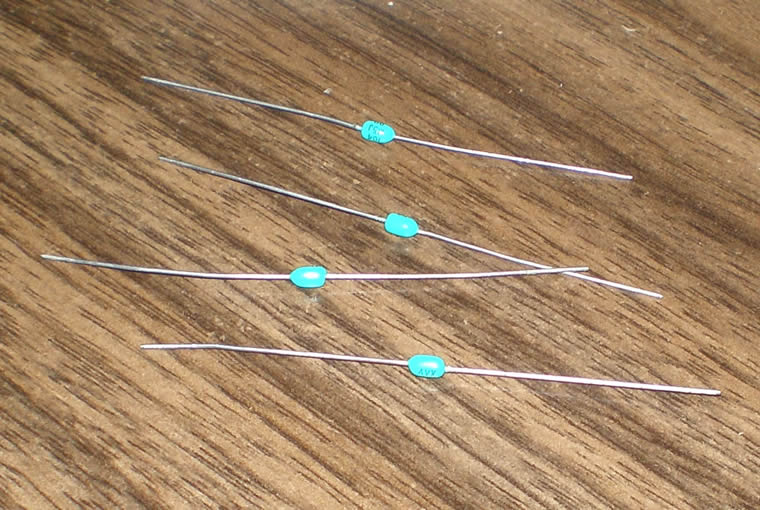
What I had been reading on the original ones on the board was a little off. On these caps you’ll see printed AVX 104 M5J 911. I don’t know what most of that means, other than 104 is synonomous with the .1 on the schematic. However, they don’t have the typical signs for polarity, and since they are caps and caps have always had polarity in my experience I will have to figure that out before putting it on the board.
Bob emailed me back right away, he is so great like that, and let me know that these caps don’t have a polarity on them, so either way is fine. I did just that and soldered the cap onto the board.
I powered up the game, and it seems to be working fine. It didn’t reset on me when I played, so that is great news. However, it does still have the lines through the screen so the next step will be a cap kit. I also thought that the one and two player buttons were a bit sticky, and the game voice seemed a little weird, like it was repeating. I have to test the Mame version and see what that does, hopefully that will give me a good indication. Otherwise I can go to Robert’s and test his Wizard of Wor to see how the voice piece works in his.
Wizard of Wor .1 microfarad capacitor
Called over to Menuier with my new found information. Once I said my Wizard of Wor PCB needed a “.1 microfarad ceramic cap” she knew right away what that is. She said they did have them. So hopefully I can make it over there on Monday to get a couple.
Wizard of Wor Capacitor Problem
I got a tremendous reply about my Wizard of Wor capacitor problem. A number of the collectors emailed me back and said they could provide me with photos. Another one went one step further and helped me identify from the schematic that it was indeed a capacitor I needed and what it is called.
On the schematic (Page 166 in the PDF online document) within the shape of the component there is a hand written .1. That means squat to me. I didn’t see a corresponding components “shopping” list with the diagram, only a list of the IC’s and other chips. Well, this collector let me know that usually .1 means that it is a “.1 microfarad ceramic cap”. That doesn’t give me a voltage, but that was specific enough.
Component C21 is what was burnt up and exploded.