
Column 10 – Part 1
CAD Interface part 2
Once again, Carl Sepura is this month’s guest columnist. Read more about him in his bio on the sidebar.
On to the article already you bozo.
This is a fantastic and very thorough article on CAD. This will not be useful to my parents, or their friends, but will be to anyone with a serious mind about learning CAD. If nothing else read it for Carl’s strong voice and engaging writing. He has done an excellent job in explanation and visual notations, so without further delay, Carl take it away.
CAD chimp part 2
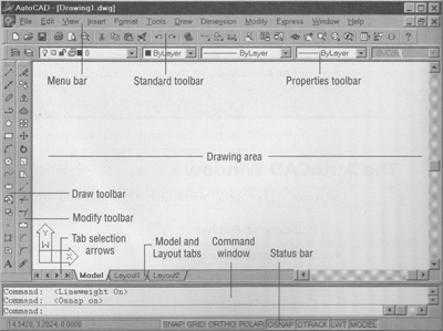
Last time we explored the basics of AutoCAD and similar CADing programs. This time around, I teach you the importance of CAD Layers, how to print what you’ve drawn, and a few tips to speed up production.
Layers
CAD drawings can become laden with information. To help a user sift through the array, CAD provides a user with layers. If you can imagine a drawing as a pile of acetate transparencies, layers enable a user to put specific items on different sheets.
These can be helpful, say, if you’re drawing a home that displays plumbing, mechanical, and electrical elements. When your plumbing contractor needs to have a document telling him where pipes need to be placed, as the draftsperson you can simply turn off the non-applicable layers and print it.
But layers go beyond acting as light switches.NOTE Within layers, a user can manipulate layer attributes: colors, lineweights (i.e. thicknesses), linetypes (e.g. dashed or solid), visibility, alterability, etc. Layers can be accessed through any of the four CADing techniques as mentioned in my last column. The simplest manner, however, is by an icon displayed in the extreme left of the Properties toolbar. To edit or create layers, click the second, colorized icon.
Note: Although turning off and freezing layers performs the identical action of making a layer invisible, the former still permits a user to edit that layer. To make sure you don’t screw up a drawing, disregard the lit/dark (on/off) light bulb icon and only use the sun/snowflake (thaw/freeze) icon. These icons are accessed by clicking the drop-down menu just to the right of the layers icon mentioned above and pertain to each layer independently.
Plotting
If you want a quick plot (CAD’s word for print) of something where precise scale is unnecessary, you can plot using any of the four general methods as described in my last column. (I happen to be partial to the Control-P keyboard shortcut.)
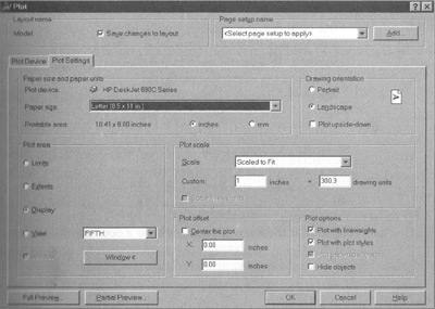
When the Plot dialog box appears, specify your printer in the Plot Device tab. Next, select the Plot Settings tab and specify the Paper size and Drawing orientation. To make sure you plot what you want, press the Window button in Plot area. The Plot dialog box will disappear and you see your drawing.
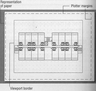
Using the cross-hairs, click and drag a box around what you want to plot. After a second click the Plot dialog box will reappear. To make sure the contents you have just boxed will fit on your paper, press the Full Preview button in the lower left corner of the Plot dialog box. CAD will work for a moment and then display a sample showing you how the drawing will appear on your printer output.
If things are a go, either press ESC to return to the Plot dialog box and press OK, or right click and select Plot from the pop-up menu. If the scale is off, or if what you need to see is not entirely viewable, you can alter the drawing’s scale within the Plot scale portion of the Plot dialog box or repeat the Window selection process. With quick plots, the quickest way to get a viewable scale is to select Scaled to Fit.
If precision is of greater importance, take note of the drooping tabs at the left-hand bottom of the drawing area. The tabs are labeled Model,
Layout1, and Layout2. The Model tab represents model space–where you draw. (Unless you have been adventurous, up to this point, everything you have done has been accomplished here.)
Subsequent Layout tabs (you are able to create more through the menu bar and a sequence of cascading menus) enable you to create different presentations of what you have drawn in Model space. Even though you can plot from Model space, Layout space eliminates the guess work.
The first time a Layout space tab is selected, CAD prompts you with a Page Setup dialog box. Herein you specify the printer to be used and the page size you will plot on. This may seem a bit repetitive if you have previously plotted in Model space. No worries, however–completing the dialog box presents you with a somewhat different appearance.
Here are some similar arcade posts
- Column 10 – Part 2
- Column 9 – Part 2
- Photoshop tutorial for punching text ‘effect’ out of an image
- Column 9 – Part 1
- Sizing Your Arcade Artwork Scan
If you enjoyed this post, please consider to leave a comment or subscribe to the feed and get future articles delivered to your feed reader.


Comments
No comments yet.
Leave a comment
Your email address is never displayed and cannot be spammed. If your comments are excessively self-promotional you will be banned from commenting. Read our comment privacy policy.